Specifications
General
Model LA5240 & LA5280
200 MSa/s
Model LA5540, LA5580 & LA55160
500 MSa/s
Max Internal clock rate
8 external clocks can be combined to form a versatile sampling clock
External clocks
8 external clocks can be used as qualify lines
Qualify
200 KΩ || 3 pF
Impedance
Inputs are clamped through a 200 KΩ resistor.
± 150 V Continuous, 250 V Trans.
Max input voltage
< 2 ns typical
Skew
> 100 MHz
Bandwidth
Variable (-6.52V to +6.12V), each pair of pods can be set to different voltage settings
Threshold voltage
Logic High: 1.54 V to 4.54 V (variable)
Logic Low: 0 V (approximately) Maximum 0.55 V at 64 mA.
Pattern Generator output voltage
Trigger
Fully adjustable to anywhere in the buffer
Position (pre/mid/post)
16 sequential levels
Number of levels
0,1 and DON'T CARE for all channels
Conditions
Trigger on the condition becoming true or becoming false
Edge
OR,AND
Inter channel modes
Any of the inputs can be used.
External trigger input
BNC connector on rear of unit
External trigger output
LA-5240
Input / Memroy
Sampling Rate
Total Inputs
Modes
(user selectable)
16 Ch (64 KSa) @200 MSa/s
8 Ch (32 KSa) @100 MSa/s
200 MSa/s
24
1
40 Ch (32 KSa)
@ 1 Sa/s to 100MSa/s
1 Sa/s to 100 MSa/s
40
2
40 Ch (32 KSa)
@ DC to 50MSa/s
External Clock
40
3
LA-5280
Input / Memroy
Sampling Rate
Total Inputs
Modes
(user selectable)
32 Ch (64 KSa) @200 MSa/s
16 Ch (32 KSa) @100 MSa/s
200 MSa/s
48
1
80 Ch (32 KSa)
@ 1 Sa/s to 100MSa/s
1 Sa/s to 100 MSa/s
80
2
80 Ch (32 KSa)
@ DC to 50MSa/s
External Clock
80
3
LA-5540
Input / Memory
Sampling Rate
Total Inputs
Modes
(user selectable)
24 Ch (512 KSa) @500 MSa/s
500 MSa/s
24
1
40 Ch (256 KSa)
@ 1 Sa/s to 250MSa/s
1 Sa/s to 250 MSa/s
40
2
40 Ch (128 KSa)
@ DC to 80MSa/s
External Clock
40
3
LA-5580
Input / Memory
Sampling Rate
Total Inputs
Modes
(user selectable)
48 Ch (512 KSa) @500 MSa/s
500 MSa/s
48
1
80 Ch (256 KSa)
@ 1 Sa/s to 250MSa/s
1 Sa/s to 250 MSa/s
80
2
80 Ch (128 KSa)
@ DC to 80MSa/s
External Clock
80
3
LA-55160
Input / Memory
Sampling Rate
Total Inputs
Modes
(user selectable)
96 Ch (512 KSa) @500 MSa/s
500 MSa/s
96
1
160 Ch (256 KSa)
@ 1 Sa/s to 250MSa/s
1 Sa/s to 250 MSa/s
160
2
160 Ch (128 KSa)
@ DC to 80MSa/s
External Clock
160
3
LA-5240
$1700LA-5540
$2500LA-5280
$2350LA-5580
$3500LA-55160
$7500LA-5000 Logic Analyzer, Pattern Generator
The PC-based Logic Analyzers communicate with laptops or desktop PCs by USB. They offer high speed clock rates, deep buffers, and sophisticated triggering. The LA-5000 Logic Analyzers are available in 40, 80 and 160 channel versions.
The Windows software makes it easy to use the Logic Analyzer. Sharing data and printing are a mouse click away.
The USB Logic Analyzer can be configured to be a Pattern Generator with the optional pattern generator pods.
- Variable threshold voltage
Threshold range: -6.52 V and +6.12 V;
threshold types including TTL, ECL, 3V logic, CMOS, and RS-232 - Pulse measurement
- Simultaneously Captures Both State & Timing Windows
- High impedance probes
Minimize interference with circuit under test (200 KΩ by 3 pf) - External trigger output
To control other instruments (e.g. scope) - Up to 100 MHz bandwidth
- DLL library (API) - optional
- External clock input
8 high speed clock inputs featuring user-defined combinations for
flexible clock qualifier setup - Pattern generator output - optional
With rates up to 100 Mpt/s
- 40, 80, and 160 channel versions
- High speed sampling
500 MSa/s (LA-55xx) max internal clock
200 MSa/s (LA-52xx) max internal clock - Deep buffers
Up to 512 K samples per channel - 40, 80 or 160 bit wide triggering
- Data file save / export
Save and export to Excel, Word, Matlab, etc. - Logic Analyzer FrontPanel® software supports Windows
For Windows - I2C monitor Decodes
I2C serial bus commands - SPI monitor
Decodes SPI serial bus commands - Continuously variable pre/post trigger position
Combined with the large buffer, provides the power of storing up
to 512K events surrounding the trigger point
Overview
Logic Analyzer FrontPanel® Software for Windows
The timing window shows the data as waveforms with the X-axis representing time. Individual channels or groups of channels can be displayed in this view.
The software allows users to change channel order, size, position, and color.
Timing Window
Channel groups can be displayed in a numeric format or as a waveform.
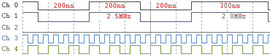
Individual pulse width and frequency information can also be displayed.
The statelist window displays the data in a numerical format with the Y-axis representing time. Individual channels or groups of channels can be displayed in this view. Data can be displayed in Binary, Hex, ASCII, Decimal or in user-defined decoding.
Statelist Window
SPI protocol data can be captured and displayed by the Logic Analyzer. It can be shown in a decoded format, as well as a waveform.
SPI Analyzer
Decoded SPI data and timing waveform display.
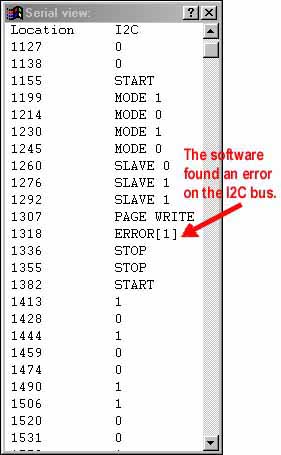
The software translates and displays captured I2C commands. What makes this product superior to other I2C monitors, is the ability to see all activity on the Clock and Data lines in Timing and Statelist display, not just the valid codes.
In addition to capturing I2C data, the Pattern Generator can be used to output I2C commands to stimulate a circuit.
The bidirectional channels of the IO-3200 allow users to capture the circuit response on the same pins.
I2C Analyzer
Seven pulse parameter measurements can be displayed for each logic analyzer channel.
Measurements include:
- Pulse Width
- Minimum Pulse Width
- Maximun Pulse Width
- Frequency
- Period
- Duty Cycle
- Pulse Count
Pulse Measurements
In theory, one would need to capture at twice their sample rate. However, in reality, the capture speed needs to be much faster than that. Our Analyzers provide up to 500 MSa/s clock rates for accurate and detailed capture.
High-Speed Operation (500 MSa/s / 200 MSa/s)
Our LA-5000 can capture long events that other analyzers may cut off. Users can also maintain higher sampling rates to get more detail without running out of buffer space.
Our buffer allows for storage of a great number of events. In some scenarios, it is difficult to pinpoint the exact event that needs to be triggered on. With our system, it is not necessary to know exactly where to trigger, since our large buffer will capture so many events.
Deep Data Buffers (Up to 512 K samples per channel)
The optional 100 Mpt/s Pattern Generator pods allow users to configure the LA as a Pattern Generator.
The output patterns can be created with our software, loaded from a file, or acquired through the input channels.
Pattern Generator
Our Logic Analyzer captures what is important. The 16 level triggering (up to 160 bits each) lets one fine tune the exact point to start capturing. Multilevel triggering can be used to look for a sequence of events (i.e. address xxxx1110xx111x0x followed by address 11xx1110xx111x0x).
Advanced Triggering
The LA-5000's can work with much higher voltages than other Logic Analyzers. The inputs are rated at ± 150 V DC continuous and 250 V DC transient.
High Voltage Inputs
The LA-5000 Logic Analyzers connect to desktop and laptop computers by USB.
USB Communication and Power
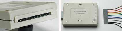
Logic Analyzer Pods
Wire harnesses:
One end of the wire harness plugs into the IO-3200, and the other has connectors for 8 channels and grounds. The wires can be connected directly to 0.025" posts on a test circuit or to our test clips.
Clips:
The double gripper is designed for hard-to-make test connections of varying sizes and shapes.
Nano-clips:
The optional Nano-clips allow users to connect to very small surface mount pins.
High Voltage Isolator:
Optically isolated input range extenders for monitoring industrial process controllers.
Accessories
In order to write their own software to drive the unit, users can buy our optional DLL library. The DLL was written in Visual C++ and includes a sample program that allows for the configuration of the LA and PG channels, data-capture, and transferal the PC.
DLL Software Library
- Data can even be shared with other computers. One can capture data in the lab and view it in your office or e-mail it to other engineers at remote locations for analysis. There is no need to be connected to our instrument in order to view a file.
- Data can be exported in "CSV" format to programs like Mathcad, Excel, Word, etc.
- Users can paste screen images into your reports using programs like Word, Excel, image editors, etc.
